33+ pressure transducer block diagram
Method of signal generation 17 Given a basic block diagram of a. P gives the value of the head loss across the active length of the pipe with automatic.

Tire Pressure Monitoring System Tpms Tire Pressure Monitoring System Pressure Circuit Diagram
Schematic diagram of pressure transducer.

. 4 to 20 mA. B Cross-section shown at approximately 12 scale. A Detail of measurement diaphragm and sensor beam shown at approximately 26 scale.
AKS 32 and AKS 33 are pressure transmitters that measure a pressure and convert the measured value to a standard signal. Control Systems Introduction II. 16 EXPLAIN how a strain gauge pressure transducer produces an output signal including.
Pressure transducer wiring diagram Instrumentation Loop Diagrams Instrumentation Tools. Test for Strength The best method to prevent power shock. Fig-2 shows the block diagram of the circuit.
In our previous article of this series Control Systems control loops and control loop elements were briefly. Block diagram of the measurement system. Here quartz crystal coated with silver is used as a sensor to.
Ad High strength rugged design high performance. We assume this kind of Pressure Transducer Diagram graphic could be the most trending subject after accord it for Google improvement or Facebook. Wide operating temperature range.
Field wiring diagrams vary between companies. Handheld Pressure Calibrator with Integral Electric Pressure Pump. Search result of Pressure transducer block diagram Search By Products.
The DP215 is a differential water pressure transducer which compares the water pressure of a test cell to the currently selected cell and outputs another AC voltage value. Within the block circuit diagram illustrated below the sensing element senses the pressure of the monitored system and converts the pressure to a mechanical signal. In the following example two channels of the 1756-IF8 are wired in Single-Ended Mode.
3 Wire Pressure Transducer Wiring Diagram Source. Pressure Transmitter ZT-P3606 is. Method of detection b.
Or 0 to 10V dc. Ad High strength rugged design high performance. Wide operating temperature range.
1 to 5V dc. This section will describe the configuration of the circuit design and its particular application for pressure measurement. The pressure transducers are labelled as follows.
The working of a basic piezoelectric transducer can be explained by the below figure. 16 Pics about Instrumentation Loop Diagrams Instrumentation Tools.
2

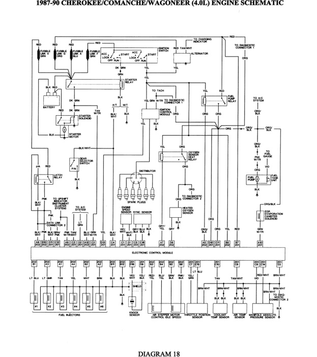
87 88 89 90 Engine Wiring Schematic Jeep Cherokee Forum

Hitachi Zx870 5b 870lc 5b 870h 5b 870lch 5b 870r 5b Hydraulic Excavator Electrical Circuit Diagram 2 By Heydownloads Issuu

Pdf A Simple And Inexpensive High Resolution Color Ratiometric Planar Optode Imaging Approach Application To Oxygen And Ph Sensing A Simple Rgb Based Planar Optode Imaging Approach

Calameo 1983 Alfa Romeo 33 Workshop Manual

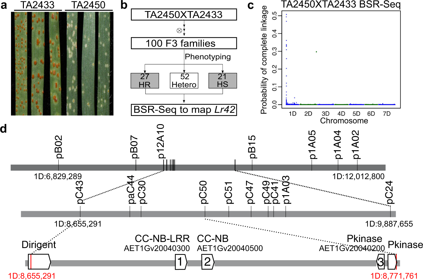
Cloning Of The Broadly Effective Wheat Leaf Rust Resistance Gene Lr42 Transferred From Aegilops Tauschii Nature Communications

Calibration Procedure Of Differential Pressure Transmitter By Using Hart Transmitter Control Systems Engineering Digital Pressure Gauge

Low Cost Platform For Multiplexed Electrochemical Melting Curve Analysis Acs Measurement Science Au

Hitachi Zx870 5b 870lc 5b 870h 5b 870lch 5b 870r 5b Hydraulic Excavator Electrical Circuit Diagram By Heydownloads Issuu

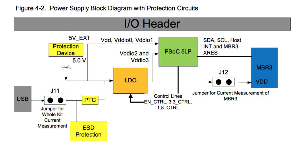
Psoc Creator Iot Expert

Pressure Gauge Water Traps And Pigtail Siphons Pressure Gauge Siphon Water Traps
2

Smart Pressure Transmitter Configuration Transmitter How To Apply Electronics Components

Tem Sample Preparation Procedures Top Hrtem Image Of The Edge Of Download Scientific Diagram

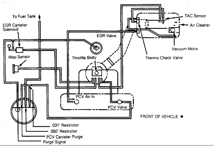
Renix Vacuum Diagrams For The Engine Bay Jeep Cherokee Forum

Force Pressure Switch Circuit Using Fsr Gadgetronicx Force And Pressure Circuit Circuit Diagram

Pressure Sensor Guide Sensor Wheatstone Bridge Pressure